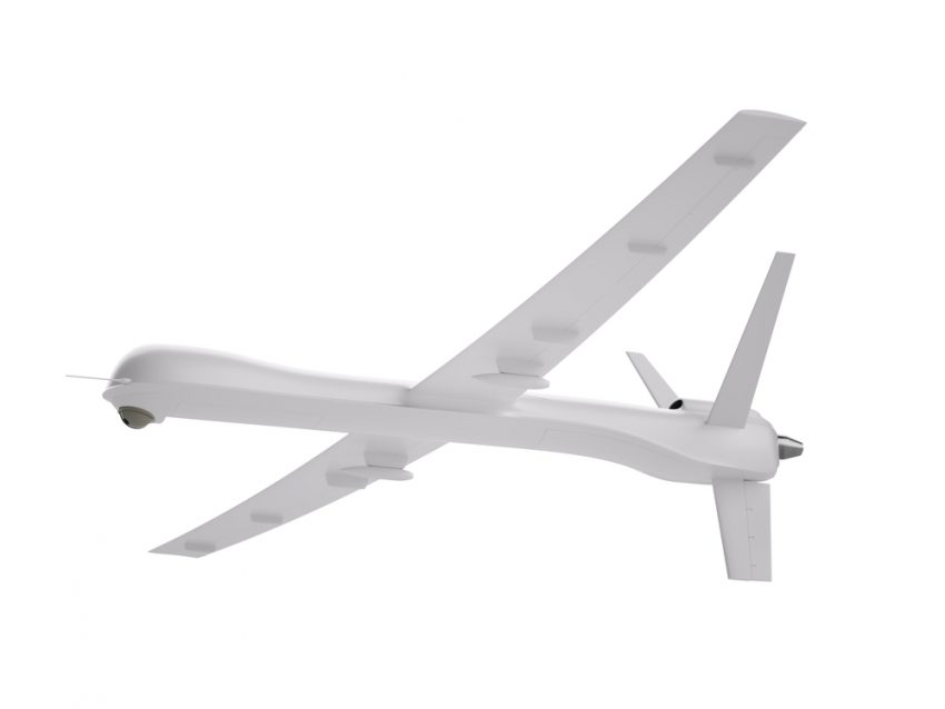
AeroVironment’s Global Observer is an unmanned aircraft with the wingspan of a Boeing 767 but less than 10% of the weight designed to provide communications and sensing for flights lasting up to one week at up to 65,000 feet. With a maximum wing loading of only 3.5 pounds per square feet, the wingtip deflects greater than 22 feet at its design limit load.
MSC Nastran was utilized to develop nonlinear stress, structural dynamic and aeroelastic finite element models. The structural dynamics model was correlated to a ground vibration test, both of which had to accommodate the apparent mass of the air, which is atypical. The ultimate test of the nonlinear stress model was correlation with the static wing load test.

175 Foot Wingspan of the Global Observer
Unusual Design Provides Unique Capabilities
The Global Observer is designed to fly at an altitude of 55,000 to 65,000 feet for 5 to 7 days. In addition to flying above severe weather and conventional aircraft, operation at this altitude permits communications and sensor payloads on the aircraft to service an area on the surface of the earth up to 600 miles in diameter. The system is intended to provide mission capabilities that include persistent communications relay, robust observation over areas with little or no existing coverage, the ability to relocate as required by theater commanders, dedicated communications support to other unmanned aircraft systems and tactical, on-station weather monitoring and data support.
The unique capabilities of the Global Observer are provided by its unusual design in which a plane with a 175 foot wingspan is propelled by less than 100 horsepower. The complex design of the primary structure provides maximum strength and tailored stiffness at minimum weight, but also presents an enormous analysis challenge. The primary structure utilizes several combinations of graphite-epoxy, honeycomb and foam core materials that are highly tailored to meet the strength and stiffness requirements while simultaneously minimizing weight. The wing was tested to design limit loads and the fuselage tested to destruction.
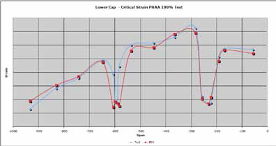
Physical measurements and finite element analysis predictions for strain on the lower spar cap
Modeling the Global Observer
The first step was importing the solid CAD models into the Patran modeling environment. MSC products were used to generate aerodynamic loads for input into the stress model. For the ground-generated loads, an optimized composite landing gear model was used. The generation of the various structural models relied heavily on the composites modeling capabilities of Patran. In general, standard elements and standard modeling techniques were used throughout. Composite shell elements with offsets were used to model the thin laminate structure. Solid elements were used for thick laminates and for the core.
Breakout models were used for the rib-skin, rib-spar interfaces, control surface interfaces and motor mount interfaces as well as others. The software automatically interpolates between the relatively coarse mesh density of the global model and the much finer mesh density of the breakout model. This approach greatly increased the accuracy of the results while keeping solution time at a reasonable level.
A Department of Defense (DoD), National Aeronautics and Space Administration (NASA) and AeroVironment team performed a series of wing load tests using a specialized fixture to apply loads to the 175 foot wing. The purpose of wing load testing was to demonstrate that the wing can withstand the stress experienced as a result of normal operation in turbulent air as well as requisite aircraft maneuvers. Figure 2 shows the finite element analysis predictions compared to the physical measurements of the strain along the length of the spar caps.
Correlation Demonstrates Accuracy of Model
“The correlation between the simulation prediction and the physical measurements was extremely good considering the complexity of the structure,” Taylor said. “The difference between the predictions and measurements was higher at the wing joints at spans -223, -583 and -697 inches because the global wing nonlinear model did not attempt to capture the detailed features of the structure at these locations. Disregarding these points, the error averages about 5%. This is remarkable considering the potential error of the instruments used to measure strain in the wing tests and the complexity of the structure and materials. The difference between the simulation and physical measurements for the strain of wing skin was slightly higher. The skin is harder to model accurately. Considering the magnitude of the analysis challenge and the potential for error in both the analyses and the test, the correlation is excellent.”
The MSC Nastran models of the Global Observer were used extensively during the test program. “We are making changes regularly to address issues that surface during the various test programs,” Taylor said. “The Nastran models have helped considerably in addressing these issues. For example, we might need to drill an unplanned hole for instrumentation at various locations on the structure and need to know if it may have any structural implications. Before we perform any modification, we look at the analysis or rerun the analysis with the proposed modification to ascertain the structural implications. As we transition to production the Nastran models will be used even more extensively, specifically in an optimization sense.
The correlated Nastran models give us a high level of confidence for our future design efforts on Global Observer and we fully intend to vigorously exercise the parametric design and optimization tools built into the MSC environment to take weight out of the aircraft to further enhance its performance.”


Leave A Reply