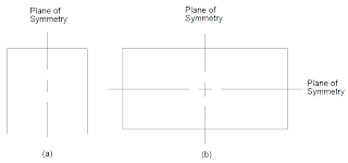
When you think of a symmetrical structure, you most likely think of a structure that has one or more planes of reflective symmetry. Although there are other kinds of symmetry available in MSC Nastran, reflective symmetry is the only type that is discussed in this section. MSC Nastran also provides a series of special solution sequences that automates some of these other types of analyses. They are known as the cyclic symmetry features and are covered in Cyclic Symmetry, 577. If a structure is symmetric, then the size of your finite element model can be reduced, which, in turn, reduces the time and cost of your analysis. For each plane of symmetry that you have in your model, the model size can be reduced by a factor of approximately two. Figure 9-29(a) and Figure 9-29(b) illustrate structures that contain one and two planes of symmetry, respectively. In the first case, only half the model needs to be represented. In the second case, only a quarter of the model needs to be represented.
 |
| Figure 9-29 Structures with Planes of Symmetry |
If the loads applied to the structure are symmetric relative to the plane of symmetry, then the full model can be replaced with half the model by applying a symmetric boundary condition. On the other hand, if the loads are antisymmetric, the same simplification can be achieved by applying the antisymmetric boundary condition.
A symmetric boundary condition implies that the displacements normal to the plane of symmetry and rotations about the axes in the plane of symmetry are zero at the plane of symmetry. An antisymmetric boundary condition implies that the displacements in the plane of symmetry and rotations normal to the plane of symmetry are zero at the plane of symmetry.
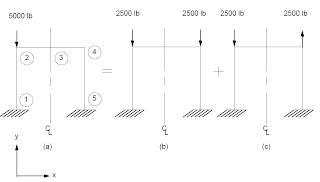
Any general loading condition can be broken into a combination of symmetric and antisymmetric loads relative to the plane of symmetry. You can work through an example of applying symmetry using the model in Figure 9-30(a). This load can be broken into two separate loads as shown in Figure 9-30(b) and Figure 9-30(c).
 |
| Figure 9-30 Decomposing a General Loading into Symmetric and Antisymmetric Loadings |
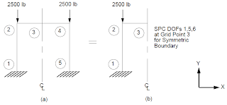
Note that Figure 9-30(a) is a case of a general loading applied to a structure with one plane of symmetry. Figure 9-30(b) and Figure 9-30(c) represent a symmetric loading and and an antisymmetric loading, respectively, applied to the same structure. By using symmetry, only one-half of the structure, as shown in Figure 9-30(b), needs to be modeled by applying the symmetric boundary condition at the plane of symmetry (see Figure 9-31).
 |
| Figure 9-31 Symmetric Model |
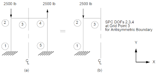
Similarly, only one-half of the structure shown in Figure 9-30(c) needs to be modeled by applying the antisymmetric boundary condition as shown in Figure 9-32.
 |
| Figure 9-32 Antisymmetric Model |
User Interface
No special user interaction is required in the Executive Control Section or Bulk Data Section. Depending on the number of planes of symmetry, approximately one-half or less of the structure needs to be modeled. For the above frame model, only one-half of the model needs to be analyzed.
This feature is activated by Case Control commands. The above frame example is used to illustrate the required Case Control commands. Listing 9-1 contains the input file for this problem. (See Install_dir/mscxxxx/doc/linstat/symbar.dat)
Listing 9-1 Input File for Using Symmetric and Antisymmetric Boundary Conditions
The first subcase selects out the symmetric boundary condition and load as shown in Figure 9-31(b). The second subcase selects out the antisymmetric boundary condition and load as shown in Figure 9-32(b).
The third subcase is a “results combination” subcase. No boundary or load conditions need to be applied for this loading condition (see Modeling Guidelines, 341 ). This subcase produces results for the portion of the structure that you have modeled (the left-hand side of the frame in this case) by performing a linear combination of the first two subcases. This combination is achieved by adding 100% of the results for the first subcase to 100% of the second subcase using the SUBSEQ command. Note that in this case of results combination, the SUBCOM instead of the SUBCASE command is used.
The fourth subcase is also a “results combination” subcase. It produces results for the portion of the structure that you did not model (the right-hand side of the frame in this case). These results are achieved by substracting 100% of the results of the second subcase from 100% of the results from the first subcase. As in Subcase 3, the SUBCOM command instead of the SUBCASE command is used in this case. Once again, no load or boundary condition is needed for this subcase; this is an optional subcase. It is not required if you do not want to obtain results for the other half of the structure that you did not model.
The displacements for SUBCOM 3 and SUBCOM 4 are shown in Figure 9-33 along with the results obtained from a full model run. The results for SUBCOM 3 (left-hand side of the frame) correlate with the full model results. The results for SUBCOM 4 (right-hand side of the frame) correlate with the full model results except for the sign changes for components x, qy , and qz The sign changes occur because the results of the right half (reflected half) are produced in terms of its left half using the left-hand coordinate system. Note that these are the same degrees of freedom that are constrained for the symmetric boundary condition.
 |
| Figure 9-33 Results Comparison Using Symmetry Versus a Full Model |
In the past, when computers were not as fast as they are now, the use of symmetry to reduce the finite element model size was more popular than it is today. The advantage of using symmetry is obviously the reduction in model size. The disadvantage is that it requires more effort on your part and it is more prone to errors since you have to provide equivalent symmetric/antisymmetric boundaries and loading conditions to your model. In MSC Nastran, the use of symmetry is built into some of the solution sequences-they are known as the cyclic symmetry solution sequences (Cyclic Symmetry, 577). Similar approaches can be used with superelement analysis.
The SYM/SYMCOM Case Control command combination can be used instead of the SUBCASE/SUBCOM combination. If you use this combination, the only changes you have to make is to replace the SUBCASE and SUBCOM Case Control commands with the SYM and SYMCOM Case Control commands, respectively. When the SUBCASE/SUBCOM combination is used, output is available in both the SUBCASE and SUBCOM subcases. On the other hand, when the SYM/SYMCOM combination is used, output requests are only available in the SYMCOM subcases. There is no real advantage to using the SYM/SYMCOM command as compared to the SUBCASE/SUBCOM command.
All of the content in this blog post has been directly extracted from the MSC Nastran 2013 Linear Static Analysis User's Guide.


Leave A Reply