Mesh transition can be a complicated subject. It may simply be used to refine the mesh in a particular area, connect different element types (for example, a CBAR element to a solid element), or provide transitions required to model the geometry of the structure. Two guidelines for mesh transitions are as follows:
- Never place a mesh transition in an area of interest or in an area where there is a large variation in stress.
- Mesh transitions should be located away from the areas of interest in a region.
Due to incompatibilities between finite element types, any transition between different element types (even a transition from CQUAD4 to CTRIA3 elements) can result in local stress anomalies. Normally, these stress anomalies are localized and dissipate quickly as you move away from the transition. However, a problem arises when the transition occurs in an area of interest. In this case, the local stress rises (or decreases) due to the effect of the transition; in other words, the results may be conservative (or unconservative) in an area near a transition. However, if this localized stress variation occurs away from areas of interest, the increase (or decrease) in stress caused by the transition should cause no concern.
Transition from a Coarse Mesh to a Fine Mesh
The transition from a coarse mesh to a fine mesh, or vice versa, may not always be an easy task. One common method of performing a transition is to use an intermediate belt of triangular elements as shown in Figure 9-8(a). It is also very tempting to selectively delete midside nodes of higher-order elements (e.g., CQUAD8) and use them as transition elements as shown in Figure 9-8(b). This method is not recommended because it severely distorts the stress distribution in the elements adjacent to the change in mesh size.
 |
| Figure 9-8 Transition Methods |
When using a higher-order element, such as a CQUAD8 or a CHEXA (nine to 20 nodes) for any purpose, the general recommendation is to include all midside nodes. A CQUAD8 element with all midside nodes deleted is excessively stiff and therefore is inferior to a CQUAD4. For the CHEXA element, you should use it with eight nodes (no midside nodes), or use it with 20 nodes (all midside nodes). The midside nodes, if used, should be located as close to the center of the edge as possible.
As an alternative mesh transition method, a spline element can be used. In MSC Nastran, the RSPLINE element is an elastic interpolation element that connects N end points. Displacements for intermediate grid points are interpolated from the equations of an elastic beam passing through these grid points. The spline element assumes a linear interpolation for displacement and torsion along the axis of the spline, a quadratic interpolation for rotations normal to the axis of the spline, and a cubic interpolation for displacements normal to the axis of the spline.
Consider an example problem as shown in Figure 9-9. This problem involves a plate fixed at the left end with a dimension of 14 in by 9 in, and modeled with 1 in by 1 in CQUAD4 elements. For clarity, only grid points of interest are labeled. Five different loadings-as shown in Table 9-2 are applied to this structure along the free edge (right end). For convenience, a RBE3 element is created along the free edge by defining a dependent point (grid point 500) at the center. This grid point is connected to all the edge grid points. The load can then be applied to grid point 500 and distributed to the rest of the edge grid points. See The RBE3 Element, 327 for a description of the RBE3 element.
Hypothetically consider that you are interested in the stresses along the line one inch from the fixed edge. Since you are not interested in the stresses outside of this region, you can represent the rest of the region with a coarser mesh. Two different transition methods will be used for this purpose-one with CTRIA3s (Figure 9-10) and one with RSPLINEs (Figure 9-11). The transitions are performed along the line five inches away from the fixed edge. An additional transition is performed at x = 11 inches in order to maintain the same grid point density on the right edge for all three models. This condition assures identical load applications for all three models. Normally, this additional transition is seldom done in a real model.
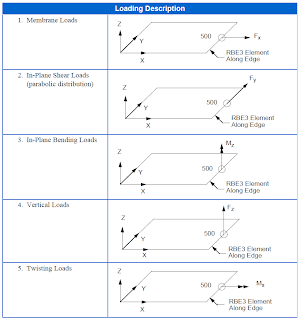 |
| Loading Description |
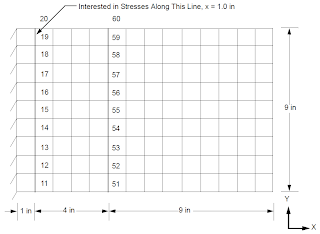 |
| Figure 9-9 Baseline Model |
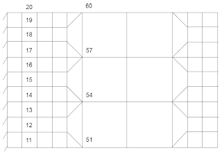 |
| Figure 9-10 Transition with CTRIA3 |
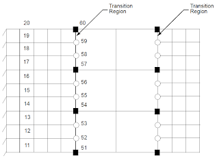 |
| Figure 9-11 Transition with RSPLINE |
The model with the mesh transition using CTRIA3s, as shown in Figure 9-10, is quite straightforward and needs no further explanation. However, further discussion is warranted in the case of mesh transition using the RSPLINE element.
The input format for the RSPLINE element is as follows:
RSPLINE
Remarks:
1. The first and last grid points must be independent.
2. Displacements are interpolated from the equations of an elastic beam passing through the grid points.
A single RSPLINE is used to connect grid points 51 through 60 as shown in Figure 9-11. Grid points 51, 54, 57, and 60 are considered to be independent, while the other six points are dependent (grid points 52, 53, 55, 56, 58, and 59). This RSPLINE interpolates the motions at the intermediate points, indicated by circles in Figure 9-11 (grid points 52, 53, 55, 56, 58, and 59), from the cubic equations of a beam spline passing through the points indicated by squares (grid points 51, 54, 57, and 60). The input for the RSPLINE element connecting grid points 51 through 60 is as follows:
The results using these two transition methods are compared with the baseline model with no transition. These results are evaluated at two locations: at x = 1.0 in (location of interest) and at x = 5.0 in (transition region). The five different loading conditions mentioned previously were used. The Hencky-von Mises stresses using the grid point stress feature (Grid Point Stresses, 376) and the CQUAD4 corner stress option are used for comparison. The results are shown in Figure 9-11 through Figure 9-16. As you can see, the results compare well, using either method of transition, with the baseline model at the area of interest (away from the transition region) for all five loading conditions.
At the transition region, depending on the loading and location, the transition using CTRIA3 elements compares better with the baseline model in some cases, whereas the transition using RSPLINE elements compares better with the baseline model in other cases. Note that there are only four stress values available in the case of using CTRIA3s since there are only four grid points along the line joining grid points 51 through 60 in Figure 9-10.
The CTRIA3 elements used in this model are all regularly shaped elements; in most real-life problems, it is very likely that the transition areas may consist of CTRIA3 elements that are more distorted. In this case, the transition using the distorted CTRIA3 elements does not perform as well as the model in consisting of regularly shaped CTRIA3 elements.
In either case, there are noticable differences in the stresses at the transition region, as expected. However, at the area of interest and away from the transition region, the stresses are virtually the same for both cases as compared to the baseline model. Once again, mesh transitions should always be modeled away from the area of interest.
Mesh transition can also be made with CINTC elements for connection meshes on dissimilar edges. Linear contact methods may also be used.
 |
| Figure 9-12 Resultant Stresses for Membrane Loads |
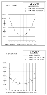 |
| Figure 9-13 Resultant Stresses for In-Plane Shear Loads |
 |
| Figure 9-14 Resultant Stresses for In-Plane Bending Loads |
 |
| Figure 9-15 Resultant Stresses for Vertical Loads |
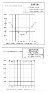 |
| Figure 9-16 Resultant Stresses for Twisting Loads |
Mesh Transition Between Dissimilar Element Types
Attaching a plate or bar element to a solid element is a case of transition between dissimilar element types. This process is more involved than it appears at first glance. Solid elements have stiffness only in the translational DOFs at the attachment grid points; they have no stiffness for rotational DOFs. A simple visualization is to think of the attachment of a solid element to a grid point as a “ball-and-socket” joint, that is, translational forces may be transmitted, but no moment may be transmitted through the connection.
This incompatibility of the element stiffness matrices represents a modeling problem whenever plate or bar elements are attached to solid elements. Both plate and bar elements have stiffness for rotational DOFs (although the plate element may not have a stiffness for the normal rotation). Therefore, special modeling must be performed whenever a plate or bar is connected to a solid element. Otherwise, the connection becomes a hinge (for plate elements) or a pinned connection (for bar elements).
Several methods are available to handle the transition between these elements. These methods range from adding extra elements (for example, adding an additional plate or bar that continues into the solid element) to using special (R-type) elements for the transition.
One method of handling this transition is to use RBE3 elements (see R-Type Constraint Elements (Ch. 8)). The RBE3 is an interpolation element, which is ideally suited for this application. By using RBE3s, the rotations of the attached grid points is simply slaved to the translations of the adjacent grid points. Examples of using RBE3 elements to connect a solid element to a plate element and bar element are shown in Figure 9-17. The RBE3 elements attach the rotational DOFs to the translational DOFs on the solid element.
 |
| Figure 9-17 Typical Transition Between Dissimilar Elements |
For the plate to solid connection, two RBE3 elements suffice:
RBE3
For the bar to solid connection, one RBE3 element can make the connection:
These RBE3 elements transmit the loads to the independent DOFs. If RBE2 elements areused, then the connection is “rigid.”
The important thing to remember when handling these connections is that the solid elements have no stiffness for rotational DOFs, whereas the real structure does. This means that a special modeling effort is needed when any element with bending stiffness is connected to a solid element.
When using the RBE3 element, care must be taken to ensure that the independent DOFs are sufficient to transfer any applied loads. For the bar-to-solid connection in Figure 9-16, if only two independent grid points are used, the element is “unstable,” that is, since only the translational DOFs are used as independent DOFs in the sample, the element is unstable for rotation about the axis connecting the two points. Therefore, three non-colinear grid points are used. A simple way to remember this is to ask, “If I constrain the DOFs that I list as independent on the RBE3, can I prevent any possible rigid body motion?” If the answer to this question is “yes,” then the RBE3 element is capable of transferring any applied loads. In this way, you can avoid possible problems in processing the RBE3 elements.
Shell-to-Solid Transition Element (RSSCON)
The RSSCON for modeling shell-to-solid transition eliminates the need to define RBE3s or MPCs (multipoint constraints) to constrain a shell element’s translational and rotational degrees of freedom to a solid element’s translational degrees of freedom. When using the RSSCON capability, the shell element mesh must line up with the solid element mesh so that there is an exact element-to-element correspondence.
 |
| Figure 9-18 Clamped Connection of a Shell to a Solid |
The RSSCON Bulk Data entry supports both p-adaptive elements and h-elements. The p-adaptive elements are outside the scope of this user’s guide. Through the RSSCON Bulk Data entry, the shell elements CQUAD4, CQUAD8, CTRIA3, CTRIA6, CQUADR, and CTRIAR can be connected to the solid elements CHEXA, CPENTA, and CTETRA. Elements with midside nodes are also supported.
RSSCON generates a multipoint constraint, which puts the shell degrees of freedom in the dependent set (m-set). The three translational degrees of freedom and the two rotational degrees of freedom of the shell edge are connected to the three translational degrees of freedom of the upper and lower solid edge. Poisson’s ratio effects and temperature loads are modeled correctly. The generated multipoint constraints produce six zero-energy modes for rigid-body motion.
The RSSCON Bulk Data entry defines the connection of a shell element to a solid element. Details are described in the Bulk Data entry RSSCON (p. 3124) in the MSC Nastran Quick Reference Guide. Within MSC Nastran, however, there are two options for making this connection using the RSSCON Bulk Data entry, as shown in Figure 9-19:
- The ELEM option, which allows you to specify the element ID of the shell and the element ID of the solid to which the shell is to be connected.
- The GRID option, which allows you to specify the grid point ID of the shell and the upper and lower grid point IDs of the solid. Two triplets of grid point IDs may be specified on one RSSCON Bulk Data entry.
 |
| Figure 9-19 ELEM and GRID Option on the RSSCON Bulk Data Entry |
The best modeling practice is illustrated in Figure 9-20. The height of the connected solid element should be chosen equal to the thickness of the shell. If the height of the connected solid element is much larger than the thickness of the shell element, then the connection modeled with RSSCON will be stiffer than the continuum model. For example, in a mesh where shell grid points are identical or coincide with solid grid points, the RSSCON Bulk Data entry may model a connection that is too stiff (see Figure 9-21[a]). Note also that in the model of Figure 9-21[b], the GRID option must be used to connect a shell element to more than one solid element.
The RSSCON connector element can accommodate a variety of mesh topologies, as shown in Figure 9-22.
 |
| Figure 9-20 Best Modeling Practice for RSSCON |
 |
| Figure 9-21 RSSCON in Meshes Where Solid and Shell Elements Share Grid Points |
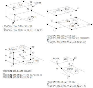 |
| Figure 9-22 Modeling Options with RSSCON |
The only modeling requirement is that the shell grid point must lie on the line connecting the lower and upper solid grid points. By default, the RSSCON allows the shell grid point to have an offset from this line of up to 5% of the distance between the two solid grid points. If a shell grid point does not lie on the line joining the two solid grid points, but within this 5% tolerance, the shell grid point will be moved to lie on the line. On the other hand, if a shell grid point lies outside this 5% tolerance, the run terminates with a fatal message. The default 5% tolerance can be modified by adding “param,tolrsc, e” to the Bulk Data Section, where ??is the desired tolerance percentage. The default value for ??is 0.05. The old and new location of the moved shell grid points can be printed using the parameter “param,sep1xovr,16".
When the GRID option is used, MSC Nastran does not verify that the grid points are valid shell or solid grid points. When the ELEM option is used, if a solid-shell connection has horizontal edges that are curved in the shell plane, MSC Nastran assumes that the geometry of the shell element is compatible with that of the solid element. In the case of vertical edges, the shell element grid point must lie on the line between the upper and lower solid element grid point. A default offset tolerance of 5% (user modifiable via "param,tolrsc,e") of the distance between the solid grid points is allowed. For limitations of the RSSCON related to the p-elements, see Rigid Elements and Multipoint Constraints (R-type, MPC) (p. 150) in the MSC Nastran Reference Manual.
By default, the moved shell grid points are not printed.
 |
| Figure 9-23 RSSCON Modeling Practice Parameters |
RSSCON Modeling Recommendations
The RSSCON connector produces excellent results if the user follows good modeling practices. The geometry of the RSSCON connector is checked, and fatal messages are issued for invalid connections. Additional recommendations are given below.
- Midside-noded elements should only be connected to other midside-noded elements. For example, a CQUAD8 element connected to a CHEXA20 element is acceptable; however, a CQUAD4 element connected to a PENTA15 element is not allowed. Elements with missing midside grid points are not allowed.
- For midside-noded elements, avoid using the RSSCON where shells connect to triangular solid faces.
- Do not mix coordinate systems when using midside nodes. In other words, when using midside nodes, do not define a local coordinate system containing all the shell grid points and the basic coordinate system to define the solid grid points. Otherwise, incorrect answers will be generated.
- Only one edge of a single shell element may connect to a solid surface.
- Do not connect more than one shell element to one solid element when using the ELEM option.
- Do not attempt solid-shell connections to severely warped (greater than 20%) midside-noded solid elements.
- The plane of the shell element should not be parallel to the plane of the connecting face of the solid element.
- The connecting edge of the shell element must lie in the face of the solid element. In addition, the vertex grid points of the shell edge connecting to a quadrilateral solid face must line up with its opposite edges; for triangular solid faces, the connections may be made between any of the edges. The tolerance in the geometry may be modified; see PARAM,TOLRSC,e described above.
- When using the ELEM option in the case of partioned superelement Bulk Data, you must ensure that the solid element, RSSCON connector, and shell element which define a shell-solid connection are all contained within the same superelement.
Cantilever Clamped to Wall
A cantilever (4.1 in long, 0.1 in thick, 0.5 in wide) is clamped to a wall and loaded at the tip. This example demonstrates how accurate the local stress distribution is when a RSSCON entry is used to model the clamped condition. Four different finite element models are used, and their results are compared with classical beam theory. The deflection and bending stress from beam theory are 0.1103 in and 9,840 psi, respectively, at the clamped end of the cantilever.
- The first model is a plate model consisting of all CQUAD4s. (See Install_dir/mscxxxx/doc/linstat/quad41.dat)
- The second model is a plate model consisting of all CHEXAs. (See Install_dir/mscxxxx/doc/linstat/hexa1.dat)
- The third model is a plate-solid model using MPCs to transition between the plate and solid model. (See Install_dir/mscxxxx/doc/linstat/mpc1.dat)
- The fourth model is a plate-solid model using RSSCONs to transition between the plate and solid model. (See Install_dir/mscxxxx/doc/linstat/rsscon1.dat)
An exploded view of the transition used in the third and fourth models are shown in Figure 9-24. Both the deflections and stress contours of the four models are in good agreement with the theoretical results, as shown in Table 9-3. You might want to review the contour plots in a postprocessor.
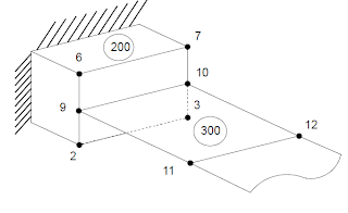 |
| Figure 9-24 Stress Distribution for CQUAD4 Model |
Table 9-2 Tip Displacements and Maximum Stresses at the Clamped End
All of the content in this blog post has been directly extracted from Chapter 9 of the MSC Nastran 2012 Linear Static Analysis User's Guide.


Leave A Reply